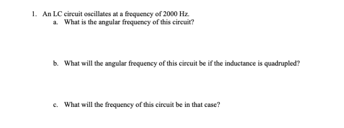
An lc circuit oscillates at a frequency of 2000 hz – An LC circuit, composed of an inductor (L) and a capacitor (C), oscillates at a frequency of 2000 Hz, a phenomenon governed by the interplay between inductance and capacitance. This resonant frequency, a crucial parameter in LC circuits, determines the circuit’s behavior and finds applications in diverse fields.
The oscillation process involves a continuous exchange of energy between the inductor and capacitor, with the circuit’s natural frequency determined by the values of L and C. Inductance, a measure of the circuit’s ability to oppose changes in current, and capacitance, representing the circuit’s ability to store electrical energy, play critical roles in shaping the circuit’s behavior.
LC Circuit Characteristics
An LC circuit consists of an inductor (L) and a capacitor (C) connected in series or parallel. The inductor stores energy in its magnetic field, while the capacitor stores energy in its electric field.
The inductance of a coil is measured in henrys (H) and is determined by its physical dimensions and the material used in its construction. The capacitance of a capacitor is measured in farads (F) and is determined by the size and spacing of its plates and the material used between them.
The relationship between inductance and capacitance determines the behavior of the LC circuit. When the inductance and capacitance are properly matched, the circuit can resonate at a specific frequency.

Resonance Frequency
The resonance frequency of an LC circuit is the frequency at which the circuit oscillates with the greatest amplitude. It is determined by the inductance and capacitance of the circuit.
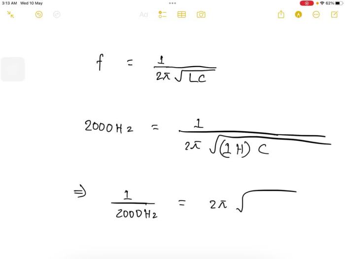
The resonance frequency (f) of an LC circuit is given by the formula:
f = 1 / (2π√LC)
where:
- f is the resonance frequency in hertz (Hz)
- L is the inductance in henrys (H)
- C is the capacitance in farads (F)
The resonance frequency is important because it determines the frequency at which the circuit will oscillate when it is disturbed.
Oscillations in LC Circuits
When an LC circuit is disturbed, it will begin to oscillate. The oscillations are caused by the transfer of energy between the inductor and the capacitor.
When the current in the circuit is increasing, the inductor stores energy in its magnetic field. When the current is decreasing, the inductor releases energy back into the circuit. The capacitor stores energy in its electric field when the voltage across it is increasing.
When the voltage is decreasing, the capacitor releases energy back into the circuit.
The amplitude of the oscillations is determined by the amount of energy stored in the circuit. The frequency of the oscillations is determined by the resonance frequency of the circuit.
Practical Applications, An lc circuit oscillates at a frequency of 2000 hz
LC circuits are used in a wide variety of applications, including:
- Radio tuners
- Filters
- Oscillators
- Resonant antennas
LC circuits are used in radio tuners to select the desired radio station. The LC circuit is tuned to the frequency of the radio station, which allows the signal to pass through the circuit while blocking out other signals.
LC circuits are also used in filters to remove unwanted frequencies from a signal. For example, a low-pass filter can be used to remove high-frequency noise from a signal.
Mathematical Analysis
The behavior of LC circuits can be analyzed using a variety of mathematical equations. The following table summarizes the key equations and their significance:
| Equation | Significance |
|---|---|
| f = 1 / (2π√LC) | Resonance frequency |
| ω = 2πf | Angular frequency |
| XL = 2πfL | Inductive reactance |
| XC = 1 / (2πfC) | Capacitive reactance |
Z = √(R^2 + (XL
|
Impedance |
φ = arctan((XL
|
Phase shift |
Circuit Design Considerations
When designing LC circuits, it is important to consider the following factors:
- The desired resonance frequency
- The available inductance and capacitance values
- The circuit losses
The desired resonance frequency determines the inductance and capacitance values that must be used. The available inductance and capacitance values may limit the achievable resonance frequency.
The circuit losses can affect the amplitude and frequency of the oscillations. It is important to minimize the circuit losses in order to achieve the best performance.
FAQ Insights: An Lc Circuit Oscillates At A Frequency Of 2000 Hz
What is the significance of the resonant frequency in an LC circuit?
The resonant frequency is a crucial parameter that determines the circuit’s behavior, including its impedance, reactance, and phase shift. It is the frequency at which the circuit exhibits maximum energy transfer and minimum impedance, allowing for efficient signal filtering and tuning.
How does inductance affect the resonant frequency of an LC circuit?
Inductance, represented by the symbol L, is inversely proportional to the resonant frequency. Increasing inductance decreases the resonant frequency, while decreasing inductance increases the resonant frequency.
What is the role of capacitance in an LC circuit?
Capacitance, represented by the symbol C, is also inversely proportional to the resonant frequency. Increasing capacitance decreases the resonant frequency, while decreasing capacitance increases the resonant frequency.